Semi Trailer Tail Lights: Inspection, Repair, and Compliance
The driver's complaint is simple: the trailer's left tail light flickers when the rig moves. You walk to the rear expecting a quick lamp swap, but the useful questions start before you reach for a replacement. Is the connector loose? Does the brake function still work? Is part of the LED array dark, and can following traffic see the lens past the discharge equipment?
For Tampa Bay fleets, that's a trailer maintenance job, not just a parts-counter transaction. A reliable repair has to address the electrical circuit, the mounting hardware, and the trailer's nighttime visibility without creating another problem during rear-panel fabrication or Walking Floor repairs.
Table of Contents
- Why Semi Trailer Tail Lights Are a Visibility System, Not Just a Bulb
- Tail Light Types and FMVSS No. 108 Requirements
- SAE J560 Wiring and Voltage-Drop Basics
- A Pre-Trip Inspection Sequence That Actually Catches Failures
- Diagnosing a Partially Failed LED Tail Light
- Step-by-Step Tail Light Replacement on a Semi Trailer
- Building a Tail Light Program That Stays Compliant Between Inspections
Why Semi Trailer Tail Lights Are a Visibility System, Not Just a Bulb
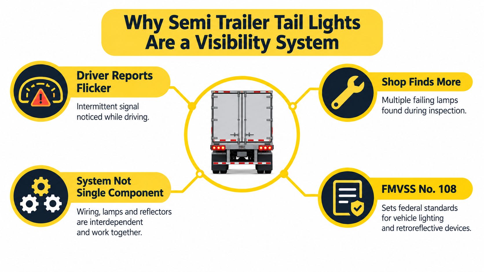
Start with the reported symptom, then inspect beyond it. A flickering lamp warrants a look at its connector, ground path, harness, mounting, and surrounding reflective markings. Replacing the visible component before checking those connections can leave the original fault untouched.
Semi trailer tail lights belong to a nighttime-visibility system. The lamps communicate operating functions, while reflective treatment helps outline the trailer under another vehicle's headlights. The mounting arrangement determines whether motorists can see either one.
This concept map shows the relationship between the driver's complaint and the broader inspection.
Start With What Following Traffic Can See
On December 10, 1992, NHTSA amended FMVSS No. 108 to require conspicuity treatment on trailers at least 80 inches wide and above 10,000 pounds GVWR; the agency estimated reductions of 25% in rear-end collisions and 15% in side-impact collisions, preventing about 2,113 crashes annually under full implementation, according to the Federal Register's account of the conspicuity rule. Those are historical regulatory estimates, not a promised result from replacing a fleet's lamps.
The practical distinction matters. A brighter replacement lamp doesn't restore torn reflective tape, and fresh tape doesn't restore a missing brake signal. Treating either repair as a substitute for the other leaves an incomplete job.
Shop rule: Diagnose the complaint at the lamp, but sign off the repair at the trailer.
For a waste hauler or aggregate operator, organize the initial assessment around the actual service configuration:
- Electrical operation: Identify which function fails and whether movement changes the symptom.
- Physical condition: Inspect the housing, rear panel, bracket, and wiring support before ordering parts.
- Visibility: Check the rear with discharge equipment and guards in their operating positions.
- Reflective treatment: Separate contamination that can be cleaned from missing or damaged material that needs repair.
That approach also keeps aluminum welding and fabrication connected to roadworthiness. A sound bracket repair must preserve the lamp's useful position, not merely hold it firmly against the trailer.
Tail Light Types and FMVSS No. 108 Requirements
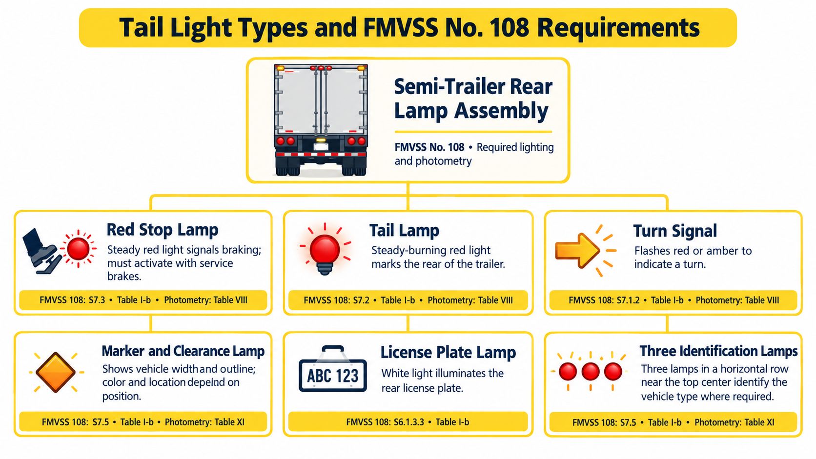
The term “tail light” often gets used for the entire rear lamp assembly. During diagnosis, distinguish the tail, stop, and turn functions from marker, clearance, identification, and license-plate lighting. Otherwise, a report that “the lights work” tells the technician very little.
Use the lamp-family diagram to organize the inspection before checking individual circuits.
Separate Function From Placement
Under 49 CFR 393.11's lighting requirements, semi-trailer tail lamps must be red, with one on each side of the vertical centerline, at the same level, spaced as far apart as practicable, and mounted 381 mm (15 inches) to 1,829 mm (72 inches) above the road. The regulation also prohibits amber stop or tail lamps, so verify emitted color during parts selection rather than relying on housing appearance.
NHTSA's trailer-lighting interpretation explains that marker lamps and reflectors apply to all trailers, rear clearance lamps apply at 80 inches or more in width, and the three identification lamps belong near the upper rear center, spaced 6 to 12 inches apart and as close as practicable to the top and center. Don't overlook those upper lamps just because the driver reported a lower rear-light fault.
| Inspection area | What the technician should establish |
|---|---|
| Tail and stop functions | Correct output color, distinct operation, and appropriate replacement function |
| Turn signals | Correct response on the commanded side |
| Marker, clearance, and identification lamps | Applicable equipment remains present and unobstructed |
| License-plate lighting | The function operates during the walk-around |
| Mounts and brackets | Repairs preserve the required arrangement rather than relocating lamps for convenience |
Treat Fabrication as a Lighting Decision
Before cutting an aluminum rear panel or fabricating a replacement bracket, record the existing lamp locations and check them against the applicable requirements. Don't assume an old installation was correct just because it survived previous service.
A recessed lamp pocket may protect the housing but conceal the lens from an angled view. Likewise, a substantial guard can be mechanically useful while creating a visibility problem. Resolve both requirements before welding, not after paint, assembly, and wiring are finished.
Use the video alongside a hands-on function check, not as a substitute for measuring the installation.
SAE J560 Wiring and Voltage-Drop Basics
A functioning brake lamp doesn't prove the tail-light feed is healthy. SAE J560 separates the truck-trailer circuits, so identify the contact involved before testing the rear harness. Use the connector's marked contact numbers and the trailer wiring diagram, not an assumed view of the socket.
The Erich Jaeger SAE J560 circuit assignments identify contact 2 for clearance, side-marker, and identification lamps; contact 3 for left turn and hazard lamps; contact 4 for stop lamps and secondary ABS power; contact 5 for right turn and hazard lamps; contact 6 for tail, license-plate, clearance, and/or side-marker lamps; and contact 7 for continuous primary ABS power or auxiliary devices, with lighting conductors generally 12 AWG and stop/ABS-secondary and primary-ABS conductors generally 10 AWG.
Confirm the ground contact and its routing from the applicable connector and vehicle documentation. Don't improvise a pin assignment or identify a circuit solely by insulation color on a repaired harness.
Measure the Circuit While It Works
Use a digital multimeter, suitable back-probing leads, and a wiring diagram. Secure the trailer and keep yourself clear of moving equipment before energizing the lighting circuit. An unloaded voltage check is a starting point, not a complete diagnosis.
For the supply-side voltage-drop test, place the meter across the feed path being evaluated while the affected lamp operates. For the ground-side test, measure between the lamp ground and the established source ground under the same load. Record the actual readings, the active function, and the test points.
A voltage reading without its load condition and reference points isn't a useful handoff to the next technician.
Don't apply an invented universal pass/fail voltage-drop limit. Compare your readings with the applicable vehicle or lamp manufacturer's specifications, then narrow the test across individual connectors and harness sections.
| Test finding | Where to investigate |
|---|---|
| Poor supply already at the tractor connector | Tractor-side feed and connections |
| Healthy connector supply but reduced voltage at the lamp | Trailer connector, junctions, splices, and harness |
| Drop along the return path | Ground terminals, conductors, and attachment points |
| Correct loaded supply and return, abnormal lamp output | Lamp assembly and its immediate connection |
Repair the identified connection, then repeat the same loaded test. That comparison is more useful than swapping lamps until the symptom disappears.
A Pre-Trip Inspection Sequence That Actually Catches Failures
The driver's walk-around and the technician's electrical inspection serve different purposes. Drivers should identify visible defects and failed functions; technicians should investigate the circuit when the report suggests an intermittent or recurring fault. Don't make live electrical probing part of an untrained driver's routine.
FMCSA's lamps and reflectors guidance requires stop lamps to activate with braking, lamps and reflectors to remain visible, and lamps other than specified temporary lamps to be securely mounted on permanent vehicle components; it also addresses retroreflective treatment for applicable trailers manufactured on or after December 1, 1993. Confirm applicability rather than treating the manufacture date alone as a complete equipment determination.
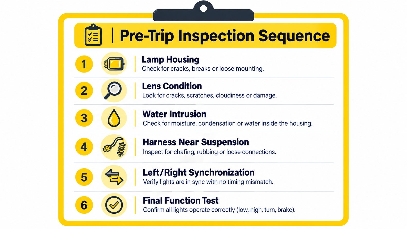
The clipboard graphic covers the core physical and functional checks.
A Clipboard-Ready Walk-Around
- Inspect the housing and mount. Look for cracked housings, loose fasteners, displaced grommets, and damaged brackets. Include the supporting rear panel, not just the lamp face.
- Clean and examine the lens. Remove residue before judging output. Note lens damage and visible moisture so the shop can distinguish contamination from an enclosure problem.
- Check accessible connections. Inspect the seven-way connector, junction points, splice seals, and ground attachments for oxidation, looseness, or damaged conductors. Route electrical concerns to a technician.
- Inspect harness movement areas. Pay attention near suspension travel points and the rear cross-member. A technician can perform a controlled flex test with the trailer secured and personnel clear of moving components.
- Operate functions separately. Check tail, stop, left turn, right turn, marker, and license-plate lighting. Compare left and right responses under the same commanded condition.
- Inspect reflective treatment. Check tape and reflectors for contamination, peeling, missing sections, and physical damage. Cleaning is appropriate for dirt; it doesn't replace absent or deteriorated material.
- Document and retest. Record the trailer identifier, symptom, affected function, repair, and final result. For electrical work, attach the loaded measurements and test locations.
A useful defect description says what happened and when. “Left tail function flickers when the rear harness is moved” gives the shop a reproducible symptom; “bad light” doesn't.
Keep unresolved findings visible through shift changes. A lamp that behaves during a stationary check shouldn't erase a documented intermittent complaint without a diagnosis.
Diagnosing a Partially Failed LED Tail Light
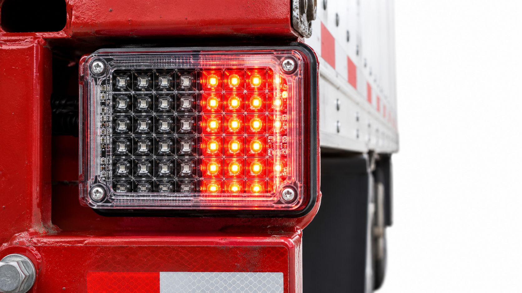
An illuminated LED lamp isn't necessarily a healthy LED lamp. A dark segment can disappear into the overall glow, particularly when the inspector looks only from directly behind the trailer. Don't clear a questionable assembly because some of its emitters still work.
NHTSA's LED interpretation records describe failures at the diode, solder, or array level that can produce dark sections or increased brightness in unaffected sections. The important implication is that visible illumination alone doesn't establish the intended light distribution.
Inspect the complete emitting pattern, not just whether the lens glows.
Compare Like With Like
Compare left and right lamps in the same operating mode. That comparison is most useful when the assemblies match; different lamp designs may have different patterns even when both are serviceable. Look for missing segments, inconsistent transitions between functions, and an unusually bright remaining section.
Then separate an internal fault from an external supply problem:
- Output changes during a controlled connector movement: Investigate terminals and the immediate harness before condemning the lamp.
- Both sides behave abnormally under combined lighting loads: Check shared supply and return paths.
- A segment stays dark with verified loaded supply and ground: Evaluate the assembly for internal failure.
- The housing contains moisture or damaged seals: Include enclosure condition in the replacement decision.
Don't use a roadside visual comparison as proof of photometric compliance. It can reveal a defect, but it can't establish that a questionable lamp still satisfies every performance requirement.
Know When to Replace the Assembly
For a sealed lamp without an approved service procedure, replace the assembly when testing supports an internal fault. Cutting it open to chase a solder joint leaves the shop responsible for a repair it may not be able to validate or reseal properly.
Release standard: Partial illumination is a reason to investigate, not permission to keep operating with uncertain output.
The trade-off is straightforward: premature replacement wastes a usable lamp, while delaying replacement after confirming internal failure leaves a known defect. Diagnose the circuit first, then make the parts decision.
Step-by-Step Tail Light Replacement on a Semi Trailer
A lamp swap should begin only after the fault has been isolated. Have the replacement assembly, compatible connector, gasket or grommet, fasteners, multimeter, measuring tape, and appropriate hand tools ready. If the bracket or rear panel needs welding, resolve that work before fitting the new lamp.
Remove and Install Without Creating Another Fault
- Secure and isolate. Park safely, prevent unintended movement, disconnect the seven-way, and isolate any separate battery or auxiliary feed according to the trailer's procedures. Verify the affected circuit is de-energized.
- Record the installation. Photograph the connector orientation, wire routing, mounting arrangement, and damaged components. Label connections when identification is uncertain.
- Remove the old assembly carefully. Support the lamp while releasing its mount. Disconnect at the plug instead of pulling on conductors, and inspect the mating terminals before reusing them.
- Prepare the mounting surface. Remove debris and address damaged edges, cracks, or distorted brackets. Don't use the new lamp to conceal an unresolved rear-panel repair.
- Fit the replacement. Match the required functions, emitted color, connector, mounting style, and available rear clearance. Seat the gasket or grommet evenly and keep wires out of pinch points.
- Tighten and support. Use the manufacturer's fastening instructions and torque specification where provided. Secure the harness with enough movement allowance for the installation without leaving it exposed to chafing.
Recheck mounting height and the left-right arrangement against the requirements established earlier. A replacement bracket should preserve compliant geometry, not place the lamp where welding access is easiest.
Verify Visibility as Well as Operation
NHTSA's rear-lighting visibility interpretation specifies at least 2 square inches of visible lens area at 45 degrees left and 15 degrees right of the lamp centerline, discusses incorporated visibility requirements through 45 degrees horizontally on both sides, and explains that additional equipment must not impair required lighting. Apply the relevant requirements to the actual installation rather than treating a single rearward view as sufficient.
Reconnect power and cycle tail, stop, left turn, right turn, marker, and license-plate functions separately. Repeat the loaded electrical test where the original fault involved wiring or connections, then inspect from the applicable viewing angles.
This is a visibility check, not a headlamp-style aiming exercise. If body equipment blocks the required lamp, don't assume a brighter auxiliary light fixes it; any corrective installation must satisfy the applicable requirements.
Finish the ticket with the installed part identification, mounting observations, electrical findings, and final functional result. Documenting those details makes a returning complaint diagnosable instead of starting the job over.
Building a Tail Light Program That Stays Compliant Between Inspections
Schedule lighting work around trailer use, not just the next shop appointment. Include visual checks before dispatch, capture defects after service, and reserve loaded circuit testing for recurring symptoms and preventive-maintenance visits. Adjust deeper inspections to the fleet's documented failure patterns rather than inventing a universal interval.
Walking Floor and aggregate trailers need a configuration check as well as an empty-trailer check. Federal rules on lamps and reflective devices prohibit obstruction by tailboards, cargo, cargo coverings, dirt, added equipment, or other material. Check the rear after loading and after body repairs, when discharge gear, guards, or accumulated residue may conceal otherwise functional equipment.
Organize the Shop Around Repeatable Repairs
- Keep usable records. Retain defect reports, measurements, parts identification, and release checks together. They support a clear maintenance history during a CVSA inspection, but they don't replace compliant equipment.
- Stock by fleet fitment. Build the shelf list around the assemblies, connectors, seals, grommets, and harness-repair materials your trailers use. Don't assume every replacement marked for trailer use fits every installation.
- Escalate structural work early. Bring in Walking Floor or aluminum-welding expertise when discharge equipment, rear-panel damage, or bracket fabrication affects the repair.
- Track repeat complaints. Review recurring faults by trailer and location so technicians investigate the shared connection or mounting problem instead of issuing another lamp.
For a Tampa Bay maintenance manager, the useful weekly priority is unresolved intermittent faults first, planned structural work coordinated with lighting access, and routine stock replenishment before the next scheduled service. That's a practical way to reduce repeated handling without promising every repair can be finished from shelf inventory.
A closed ticket should mean a verified system, not merely a new part. Keep electrical diagnosis, fabrication, and the final visibility check on the same work order.
Brothers Truck Trailer Repair and Welding Corp. offers truck and trailer repair, Walking Floor diagnostics and maintenance, aluminum welding, custom fabrication, and parts support. For a tail-light complaint involving wiring, a damaged rear panel, or discharge-equipment clearance, visit Brothers Truck Trailer Repair and Welding Corp. to discuss the trailer's symptoms and the repair and parts requirements.

15 ton trailer specs, configurations, and selection criteria for fleets. Compare axles, brakes, frames, and maintenance points before you buy or repair.

Learn proper weight distribution on trailers with practical steps for tongue weight, load placement, axle checks, and fleet inspection routines.
Technical reference for 3500 lbs trailer axles covering GAWR, tire ratings, brake rules, fitment specs, and inspection protocols for commercial fleets.